Flippingless Rigs, Euler, Matrix and Quat Theory
Most of the riggers have to face this problem very early in their riggers life: a bone that flips in some specific rotation angles. Oviously a very awful behaviour that should be avoided as much as possible, but it's not an easy task, and that's because those flippings are impossible to avoid. At some angle, in some rate, or some intensity, that flip must happen in those rigs. So.... how can this tut help to solve this problem?... well, here i'm gonna show you a way to make this flip happen only in a very hard to reach specific angle. If we have a hierarchy of bones, that angle will be the angle where the child bone rotates 180 degrees overlaping its parent, if the child bone is the arm of a character the arm has to be overlapping the shoulder to show that flip. It's a very desirable result, 'cause almost all the time that doesn't happen.
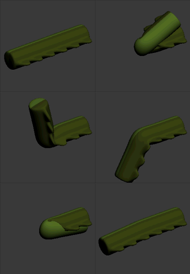
this problem is seen in two kind of rigs : twist bones, and lookat bones (and others that wont be mentioned in this tut). The first one can be setup with a lot of ways, but all of those can be summarized in only two main methods: removing the x-rotation value from the bone where this twist bone is attached, or setting up a look at constraint in the twist bone with the elbow as target. In both methods the flip will happen when the y-rotation reach and goes beyond 90 degrees or below -90 degrees, this flip angle may change depending on how the rig was set up, but as mentioned before it will always happen.
this problem is seen in two kind of rigs : twist bones, and lookat bones (and others that wont be mentioned in this tut). The first one can be setup with a lot of ways, but all of those can be summarized in only two main methods: removing the x-rotation value from the bone where this twist bone is attached, or setting up a look at constraint in the twist bone with the elbow as target. In both methods the flip will happen when the y-rotation reach and goes beyond 90 degrees or below -90 degrees, this flip angle may change depending on how the rig was set up, but as mentioned before it will always happen.
In the previous animation we can see this tipical issue happening. In order to fix it we need to have a clear insight of what is going on there. If we consider the first main method to set up a twistbone (removing the x-rotation value) the first thing that we need to know is the euler angles behaviour, because the way that we extract rotation values per axis is using euler angles. So, let's take a look at how they work.
Euler Angles Theory

With Euler angles any object orientation is given by a sequence of rotations per axis, generally this sequence has the XYZ order, that means the object is first rotated in the x-axis, then in the y-axis and finally in the z-axis. The order is always important in 3d space transforms, is not the same rotate an object in world space and then translating than translating first and then rotating in world space. The same happens with rotation axis.
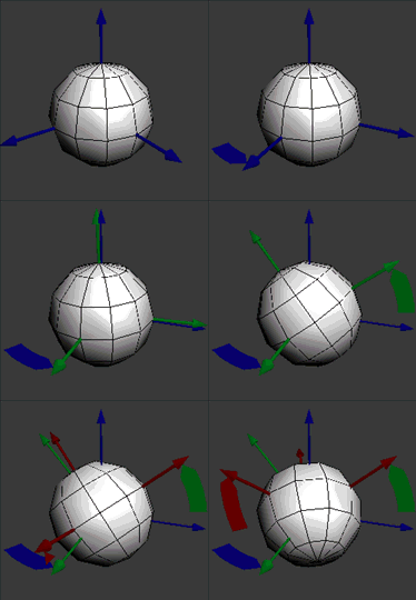
A good way to see how the euler angles work is seting the transform system to gimbal, and rotate the object around. As you can see it seems like there is a sort of axis hierarchy going on there, it seems like the x-axis is linked to the y-axis and the y-axis is linked to the z-axis. If you are wiring a rotation axis to something else and you dont know exactly what axis to use, you should set the transform system to gimbal, that is the way to go.
So... how this theory can help us to understand the flipping issue?, well, the euler angles by themselves aren't causing that problem, in fact, if you use direct wiring from an euler angle x-axis to remove the twistbone rolling, you wont get any flips, but obiously you can't do that frequently, almost all the time you need to use an ik solver in the rig or some sort of constraint. The problem happens when you get a rotation value in quats from a bone that have some sort of setup and convert that value to euler angles to extract the x-axis value.
Any given orientation can be reached with a specific range of the values stored in an euler angles rotation. Those ranges are:
X: -180, 180.
Y: -90, 90.
Z: -180, 180.
And those are the ranges that Quat to Euler conversion uses to get the result. Let's see the next animation:
As you can see above, if a rotation goes beyond 90 degrees in the y axis, the z axis flips to reach that orientation and the x-axis flips as well to compensate the z-flip. The same happens if the rotation goes below -90 degrees in the y-axis. So, if we set the x value to zero there is nothing that compensates the z-flipping that happens when the y-axis value goes beyond 90 degrees. That is the reason of the flipping happening in almost all the twist bones rigs.
Fixing the Flipping Issue in Twistbones
To continue with the tutorial download this file:
| flippingless01.zip | |
| File Size: | 13 kb |
| File Type: | zip |

This file has a 3ds max 2008 scene with three bones, those are: a shoulder, an upperarm, and the twistbone of the upperarm which is linked to the shoulder. Now we are going to find a way to fix the flipping having in mind the theory learned above.
First let's setup a basic twistbone, it should follow the upper arm rotation but without the x-axis rotation. To do so, select the object "twistbone", go to the motion panel , select the rotation track and assign it a Rotation script controller . Create a variable called "upperarm" and assign it the upperarm node (select the variable, press the add node button and select the "upperarm" node). In the Expression Box write this code (replace the text that is already there):
First let's setup a basic twistbone, it should follow the upper arm rotation but without the x-axis rotation. To do so, select the object "twistbone", go to the motion panel , select the rotation track and assign it a Rotation script controller . Create a variable called "upperarm" and assign it the upperarm node (select the variable, press the add node button and select the "upperarm" node). In the Expression Box write this code (replace the text that is already there):
theRot=(upperarm.transform * Inverse upperarm.parent.transform).rotation as EulerAngles
theRot.x=0
theRot
In the first line we're are getting the upperarm rotation respect to its parent (the shoulder) and then we're converting it to euler angles (the rotation is intially a quaternion), in the next line we set the x-value to zero and in the last line we leave the rotation value as output to the controller.
In this rig we can see the flipping happening (select the upperam and rotate it beyond 90 deegres in the y axis), to fix it we could use the z axis value to compensate the flip made by itself storing it in the x axis, but that is not the way to go because we don't want the z axis to affect the x orientation of the node. what we can do is use another axis order while converting the rotation from quat to euler, the theory is the same for any order: the second axis can't go avobe 90 degrees neither below -90 degrees, the other two axis will flip when that is required. The order that can be used is XYX, X will compensate itself to avoid the flip.
The code in the Expression Box will be as follows (replace it entirely):
theRot=QuatToEuler (upperarm.transform * Inverse upperarm.parent.transform).rotation order:7
theRot.x=-theRot.z
EulerToQuat theRot order:7
In the first line we're getting the upperarm rotation in respect to the shoulder and converting it to euler angles using the seventh order (XYX). In the Second line, in order to compensate the flip, we're storing the negative z-axis value in the x-axis (in this case the z-axis is the x axis as well, 'cause we're using the XYX order) . And finally we're converting the rotation back to quaternion using the seventh order too. In the previous script we didn't convert the rotation because the controller does it automatically (but in the first axis order XYZ).
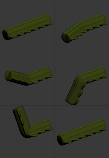
If you start rotating the bone you will notice that there is not flipping happening in the orientation that it used to happen before, the upperarm has to overlap the shoulder to show that flipping. If you set a zero rotation in the upperarm, rotate it 90 in the z-axis and rotate it around the world space x-axis you will see that the x-axis is rolling, apparently there is something wrong because the x-axis is not supossed to roll, but there is nothing wrong there, and that happen because the natural behaviour of a twist bone is not to have the x-axis still. The natural behaviour of the twist bone is to have its upper side always facing the bent direction of the upperside of the parent.
You can download the finished version here:
| flippingless01_final.zip | |
| File Size: | 14 kb |
| File Type: | zip |
Lookat Flipping Issue
Well, the previous method is pretty useful to twistbones, but what about nodes with lookat controllers? they also flip in those undesirable angles. One of the best way to fix that problem is writing our own lookat script controller.
The lookat constraint finds out the right lookat orientation by building up a rotation matrix with the given node and target position. But that algorithym has that flipping issue, the way that we can avoid that is not using a matrix to build up the lookat orientation, instead, we will build up a quaternion.
First, let's see why this flipping happens:
Matrix Theory
The matrices are always used to transform and store objects transformations in 3d space, a 3x4 matrix (also known as matrix3) is used in almost all 3d aplications. A matrix3 is a special matrix that is composed by four vectors or rows of three values, the first vector stores the direction and length of the x-axis of the node, the second vector stores the direction and length of the y-axis, the third vector stores the direction and length of the z-axis. This three vectors stores the rotation and scale of the node, for example, if the node is scaled 200% in the x axis the first vector lenght will be 2. The position of the node is stored in the fourth vector. If the matrix is a rotation matrix, the last vector should be [0,0,0] and the length of the first three vectors should be 1.
In order to transform an object several times, a matrix multiplication have to be used (the order of these transformation is important, as mentioned before). For example, when you link a node to another, the aplication internally is multiplying the local transform matrix of the child node with the transform matrix of the parent node to find the total transformation of the child node, just as follows:
T=L*P
where T is the total transformation of the node, L is the Local transform matrix, and P is the parent transformation.
The lookat constraint finds the rotation by finding the first three rows of the matrix3. Just as Follows:
row1=normalize (Target.position-Node.position)
row2=normalize (cross row1 Upvector)
row3=normalize (cross row1 row2)
In the first line a vector from the Node to the target is calculated, it defines the direction from the node to the target, this value is then normalized to make sure that the vector length is 1.
In the second line another vector is found, this vector is perpendicular to both, the first row and the Upvector (this vector is defined by the node selected as upNode), the cross product is used to find a vector perpendicular to another two vectors. Again the value is normalized.
The last vector is the vector perpendicular to the first two vectors.
The order of the rows depends on how the lookat controller was configurated.
The direction of the last axis will flip if the first axis goes from the left side to the right side of the upVector. That happens when the y-axis goes beyond 90 degrees or below -90 degrees depending on how the lookat constraint was configurated.
In order to fix the flipping issue we must understand how Quaternion works:
Quaternion Theory

A quaternion is another way to set the rotation of an object, but instead of having 3 values defining the amount of rotation per each axis, it has 4 values that defines the rotation in complex number system. The adventage of using quaternions is that they are faster to compute than matrices and its interpolation is smother than euler angles, because of that, quaternions are widely used to calculate rotations in all kind of 3d aplications. Animators preffer to use Euler angles though, With euler angles you can edit the interpolation curves per each axis using the tangent handles, with quats you can't, nevertheless, you can edit the quats interpolation using Tension, Continuity and Bias values (TCB).
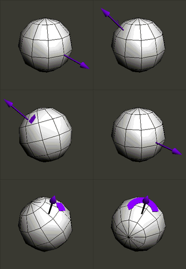
A quaternion can be built up using a vector and a scalar value. This is the AngleAxis to Quat Conversion. And that is the way that you should built up a quaternion given any case. The Vector defines the Axis where the node will be rotated, and the scalar value defines the amount of rotation on the given axis (angle of rotation). In this animated image you can see how the AngleAxis reach some orientations (the arrow is the direction of the axis).
A quaternion can be built up using a vector and a scalar value. This is the AngleAxis to Quat Conversion. And that is the way that you should built up a quaternion given any case. The Vector defines the Axis where the node will be rotated, and the scalar value defines the amount of rotation on the given axis (angle of rotation). In this animated image you can see how the AngleAxis reach some orientations (the arrow is the direction of the axis).
Fixing the Flipping Issue in Lookat Setups
Now, to get the lookat rotation without the flipping, we're going to build up the quaternion using the AngAxis to Quat conversion. If we do that we can rotate the bone from it's resting orientation to the desired lookat orientation, without getting that flip in the 90 degrees Y-axis. It will only flip in that almost unreachable orientation (the bone overlaping its parent).
To continue with the tutorial download this file:
To continue with the tutorial download this file:
| flippingless02.zip | |
| File Size: | 34 kb |
| File Type: | zip |
This file has a 3ds max 2008 scene with 3 bones, and one point helper. Those are: Spine01, Spine02, Joint and Target (the joint bone is used to keep the mesh volume). In this case we need the Spine02 to lookat the Target helper. To do so, select the object "Spine02", go to the motion panel, select the rotation track and assign it a script rotation controller . Create a variable called "Target" and assign it the Target node, then, create a variable "Parent" and assign it the Spine01 node, and finally create a variable NodePos and assign it the "Spine02" position controller (select the variable click "assign controller" find the Spine02 object, select the position track and press OK).
The code in the Expression Box will be as follows (replace the text that is already there):
The code in the Expression Box will be as follows (replace the text that is already there):
theTargetVector=(Target.transform.position * Inverse Parent.transform)-NodePos.value
theAxis=Normalize (cross theTargetVector [1,0,0])
theAngle=acos (dot (Normalize theTargetVector) [1,0,0])
Quat theAngle theAxis
In the first line we're Finding the vector that goes from the spine01 position to the target position, that vector must be in respect to the spine01 parent, to get an orientation in parent space (the way that local controllers works). the NodePos.value is already in parent space because that variable is referencing the local position controller of the spine01.
In the second line we are finding the axis in which the node should rotate to aim that position, that vector is perpendicular to the TargetVector and the x-axis (1,0,0)
In the third line we're finding the amount of rotation needed to reach the desired rotation, that value is the angle between the x-axis (1,0,0) and the TargetVector.
In the Last line we build up our quaternion using the axis and the angle.
Here you can see what we have got so far, an almost flipless lookat script controller:
You can download the finished version here:
| flippingless02_final.zip | |
| File Size: | 35 kb |
| File Type: | zip |
Ok, this is it, thanks for watching this tutorial, see you the next Time!.


