Tank Rig Tutorial
< 1 2 3 4 5 6 >
Auto Spinning Wheels
First of all, we need to create our tank's rout, so we can use the distance along this path to define the wheel's spinning. We cannot use only the tank's current position, because the wheel's spinning depends on the distance traveled by the tank. For example, if our tank goes from the point A to the point C its wheel's rotation in the point C will be diffirent if it goes from A to B and then to C, not matter that it's finally in the same place, that's because the distance is different. So, if we create a spline as its path, we may know exactly the distance traveled by the tank along this path.
|
Unhide by name the "Path" and the "Control_Main" objects, we're gonna use this last one as the point that is going to travel along the path. Select the Helper_Attached_01 and link it to the ProjectedPlane, then link the ProjectedPlane to the Control_Main, the hierarchy now goes as shown in the picture.
Align the ProjectedPlane to the Control_Main, make sure to check all position and orientation axis and that both objects are in pivot point align. The plane now looks weird, but we'll fix that in the next step. With this hierarchy we make sure the wheel and the projectedPlane will follow the Control_Main's rout and its orientation. |
|
Select the Control_Main and add it a Path_constraint, select the Path spline as target. we need to configure some settings in the motion panel. The point needs to "Follow" the path and its axis must to be "z" and flipped. with this settings the projectedPlane has a right shape, because it is now parallel to the ground.
|
The Spinning Expression
We'll need a mathematical expression in the wheel's x-rotation controller. In this expression we need to find the x-rotation value regards the distance traveled by the tank. I could give you the expression and you could use it without knowing how it was made, but i won't be a good teacher if you make it so easy!.........
Seriously speaking, It's better that you start understanding how to make expressions for future rigs challenges. So, here we go, a small and very easy mathematical lesson:
Seriously speaking, It's better that you start understanding how to make expressions for future rigs challenges. So, here we go, a small and very easy mathematical lesson:

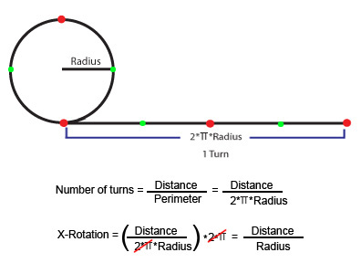
How can we find the wheel's x-rotation?. Think about the distance that a circumference needs to travel to make a full turn. This distance is equal it's perimeter (2*pi*radius).
To find the numbers of turns along a distance, we could take this distance and divide it by the distance traveled by one turn (as mentioned before, one turn is equal the perimeter). For example, if we have a distance of three times the wheel's perimeter, dividing the first value over the perimeter wil give us a number of 3 turns.
And what do we do next with the turns number?. We could multiply it by its equivalent in degrees, 360º or 2*pi in radians, and we got our expression!.
This expression goes as follows:
(Distance / (2*pi*Radius)) * 2*pi
Actually, we may cancel the (2*pi) values by themselves. 2*pi / 2*pi is equal one (1), so we can remove these numbers, they're irrelavant now.
We got: Distance / Radius.
And what about the distance? how can we find it?. we could do it using the percent along path of the path constraint, and the path's length. One value by the other will give us what we wanted: Distance=(Percent/100)*SplineLength, we divide Percent by 100 because here we need a percent that goes from 0 to 1. when the percent is 0% the distance is 0, when the percent is 100% the distance is equal the Spline's Length. 50% will give us a half of the spline's length, and so...
Finally the expression goes as follows: (Percent/100)*SplineLength / Radius.

Now, we're gonna put this expression in the wheel's x-rotation controller, we'll be using the script controller.
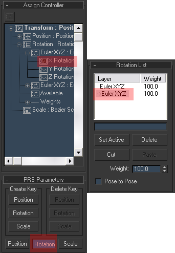
Select the wheel, in the Motion Panel open the Assign Controller rollout, select the Rotation: Euler XYZ Controller and click in the assign controller button , select Rotation List. With a list of rotations we may have 2 controller layers, one for the script and the other one for manual adjustments. Open the rotation List, in the Available controller assign an Euler XYZ controller, this controller is for manual adjusment, so we need to set it active double clicking it in the Rotation List rollout, or by clicking the "Set Active Button". When a controller is active this one will be the one that we'll be modifying by the rotation gizmo (manual adjustment).
Go back to the first Euler XYZ controller in the Assign Controller Rollout, open it, in the x-rotation controller assign a float script controller.
In the Expression Text Box write: SplineLength=curveLength Path, this line enables us to get the path's length using the curvelength maxscript function (it doesn't work well if the path spline is scaled). In the next line write the expression,(Percent/100)*SplineLength / Radius.
Then, we have to create the variables, and assign them their respective values.
In the Create Variable Group you have to write the names of the variables exactly as they're written in the Expression text box. Start writting Path, then click on the Create Button, do the same with Percent and radius.
We do not need to create the SplineLength variable because it gonna get its value inside the script.
If we evaluate the expression now, we're gonna get nothing, because we need asign the variables to their respective values.
Select Path in the Variables List and click in the Assign Node button, select the "Path" spline object in the "Track view Pick" DialogBox.
Select Percent in the Variables List and click in the Assign Track button, select the control_Main's path constraint percent controller.
Select radius in the Variables List and click in the Assign Constant button, write 0.473 (you can find it using the tape helper object measuring the wheel's diameter and then dividng by two).
You could assign the wheel's radius parameter to the radius variable if you need to change the wheels radius in the future.
If you evaluate now, we get our auto spinning system!, you can check it out by moving the control_main object.


